
In the Member Editor component, you can also select the entire member as the modifying object instead of the individual member plates. This way, you can apply both operations "Notch" and "Chamfer" to several member plates.

The "Member Editor" component allows you to modify the individual or several member plates in the Steel Joints add-on.
You can use the chamfer, notch, rounding, and hole operations with multiple shapes. It is possible to apply both operations, "Notch" and "Chamfer", for several member plates.
In this way, you can notch flanges from I-sections, for example (see the image).
Go to Explanatory Video
- Design of tension, compression, bending, shear, torsion, and combined internal forces
- Consideration of a notch
- Design of compression perpendicular to the grain on the end and intermediate supports with (EC 5) and without reinforcement elements (fully threaded screws)
- Optional shear force reduction at the support (see the Product Feature)
- Design of curved and tapered members
- Consideration of higher strengths for similar components that are close together (factor ksys according to EN 1995‑1‑1, 6.6(1)-(3))
- Option to increase shear resistance for softwood timber according to DIN EN 1995‑1‑1:NA NDP to 6.1.7(2)
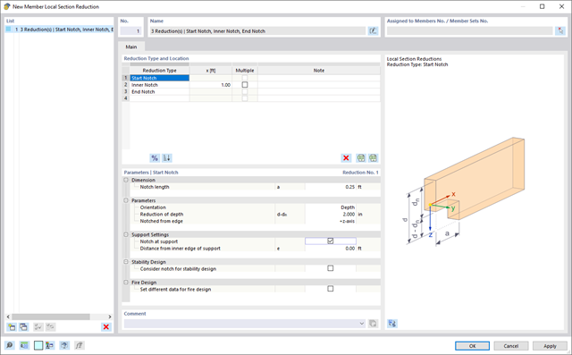
Use the member cross-section reductions to consider the start, internal, or end notches of a beam. The beam reduction is thus taken into account in the calculation of the load-bearing capacity. However, this does not apply to the stiffness.
.png?mw=640&hash=eaf8e422e9b3dcfb04a920c1d3bf09c1bef0d59a)
General
- Beam to Column joint category: connection possible on the column flange as well as on the column web
- Beam to Beam joint category: optional arrangement of ribs on the opposite side
- Bolt sizes from M12 to M36 with the strength grades 4.6, 5.6, 8.8, and 10.9
- Arbitrary bolt hole spacing and edge distances
- Notching of the beam is possible
- Connection with pure shear loading, pure normal force load (tension joint), or possible combination of normal and shear forces
- Checking compliance with the requirements for pinned joints
- Check of the minimum and maximum bolt hole spacing and edge distances
Web cleat connections
- One or two vertical and up to 10 horizontal bolt rows possible at each leg
- Wide range of equal and unequal angles
- Possible to modify angle orientation
- Designs:
- Shear, bearing resistance, and tension design of bolts
- Shear, bending, and tension design of angles considering deduction of bolt hole
- Shear and tension design of girder web considering deduction of bolt hole
- Tension transmission into the column with the T-stub model
- Notching at the critical section
Fin plate connection
- One or two vertical and up to 10 horizontal bolt rows are possible
- Flexible size of the fin plate
- Location of the fin plate can be modified
- Designs:
- Shear and bearing resistance design of bolts
- Shear, bending, and tension design of fin plates considering deduction of bolt hole
- Stability analysis of long, slender fin plates
- Shear and tension design of girder web considering deduction of bolt hole
- Weld as fillet weld
- Notching at the critical section
End plate connection
- Two or four vertical and up to 10 horizontal bolt rows
- Flexible size of the end plate
- Location of the fin plate can be modified
- Designs:
- Shear, bearing resistance, and tension design of bolts
- Shear and bending design of end plates considering deduction of bolt hole
- Shear and tension design of girder web
- Tension transmission into the column with the T-stub model
- Weld as fillet weld
- Notching at the critical section
End plate connection with cleat
- Fixation of the beam by end plate with two bolts
- Flexible size of cleat and end plate
- Designs:
- Load introduction into the beam according to EN 1993-1-5, Chapter 6
- Support of the stabilizing moment by the bolts and welds at the end plate
- Cleat
- Cleat welds as fillet welds
- Tension transmission into the column with the T-stub model
The details for the lateral-torsional buckling analysis are defined separately for members and sets of members. The following parameters can be set:
Support Type/Lateral-Torsional Buckling Load
- Available options are Lateral and torsional restraint, Lateral and torsional restraint or Cantilever
- Special supports are possible by specifying the degree of restraint βz and the degree of warping restraint β0. In this section as well, you can consider the elastic warping restraint of an end plate, a channel section, an angle, a column connection, and a beam cantilever by specifying the geometry dimensions.
- As an alternative, it is also possible to enter the lateral-torsional buckling load NKi or the effective length sKi directly
Shear panel
- A shear panel can be defined from a trapezoidal sheeting, bracing, or a combination of these
- Alternatively, you can enter the shear panel stiffness Sprov directly
Rotational restraint
- Choose between continuous and discontinuous rotational restraint
Position of Positive Transverse Load Application
- The z-coordinate of the load application point can be freely selected in a detailed cross-section graphic. (upper chord, lower chord, centroid)
- Alternatively, you can specify the data by selecting them or entering the data manually.
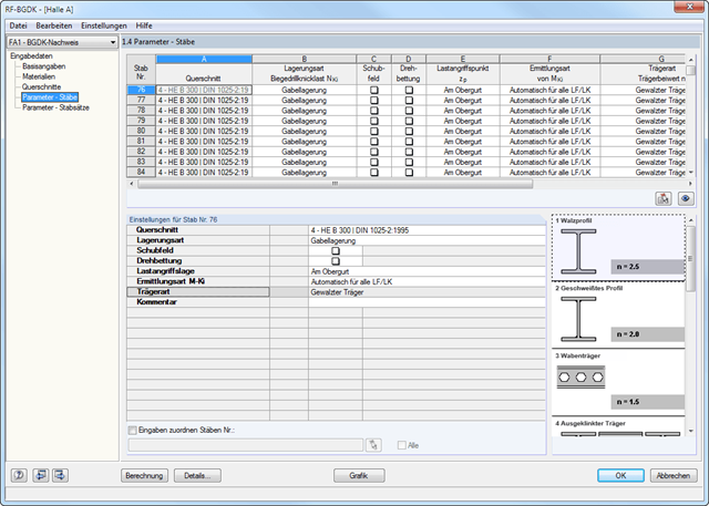
Beam Type
- For standard sections, the rolled beam, welded beam, castellated beam, notched beam, or tapered beam (web or flange welded) options are available
- For special cross-sections, it is possible to directly enter the beam factor n, the reduced beam factor n, or the reduction factor κM